Driving is hard, but humans make it look easy. We're UT Dallas's applied autonomous driving project, and we're making driving look easier than ever.
YouTube
project.nova@utdallas.edu
Latest posts
New Members and Goals! 23-24 11/15/23Planning with cost maps 2/13/23
What's up with Nova? 2/2/23
New members (and goodbyes) 10/23/22
Why we like Nova (video) 8/27/22
All posts ⟶
Rewiring Voltron
by Will Heitman
As one final push to get things ready for our fall semester, Voltron underwent a full wiring cleanup. Sketchy soldering jobs were replaced with weatherproof automotive connectors, confusing bunches of wiring spaghetti were replaced with tangle-free conduit, and new components like CAN bus chips were mounted firmly in place.
Of course clean wiring eliminates frustration, but it’s also much safer than the messy alternative. Solid and well-planned electrical connections are less prone to short circuits, brownouts, and other unwanted behavior. We felt it important to address our wiring immediately in our effort to make Voltron as safe and stable as possible.
Not much theory here! I’ll only outline a couple methods we used that were helpful.
First, we chose two common connector formats for all of our connections. First we chose Deutsch DTM connectors, which are popular in production cars due to their rugged, weatherproof design. Second we chose the ubiquitous 0.093 inch Molex connectors, which are found in everything from PC motherboards to pinball machines. They’re not nearly as tough as DTM connectors, but they’re less expensive and complicated.
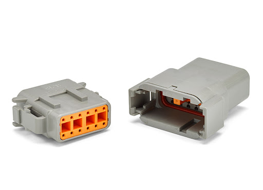
DTM connector plug and socket (TE Connectivity)
Second, we wrapped major wire clumps into flexible split conduit. We then routed this conduit around the vehicle’s chassis and attached it to the car’s body using hook-and-loop wrap. Slightly more permanent attachments were made using zip ties.
Third, we left room for modification and expansion. We used solder sparingly, only in connections that we were sure wouldn’t change. Our flexible solder alternatives ranged from wiring nuts to “quick disconnects” to the DTM and Molex connectors outlined above.
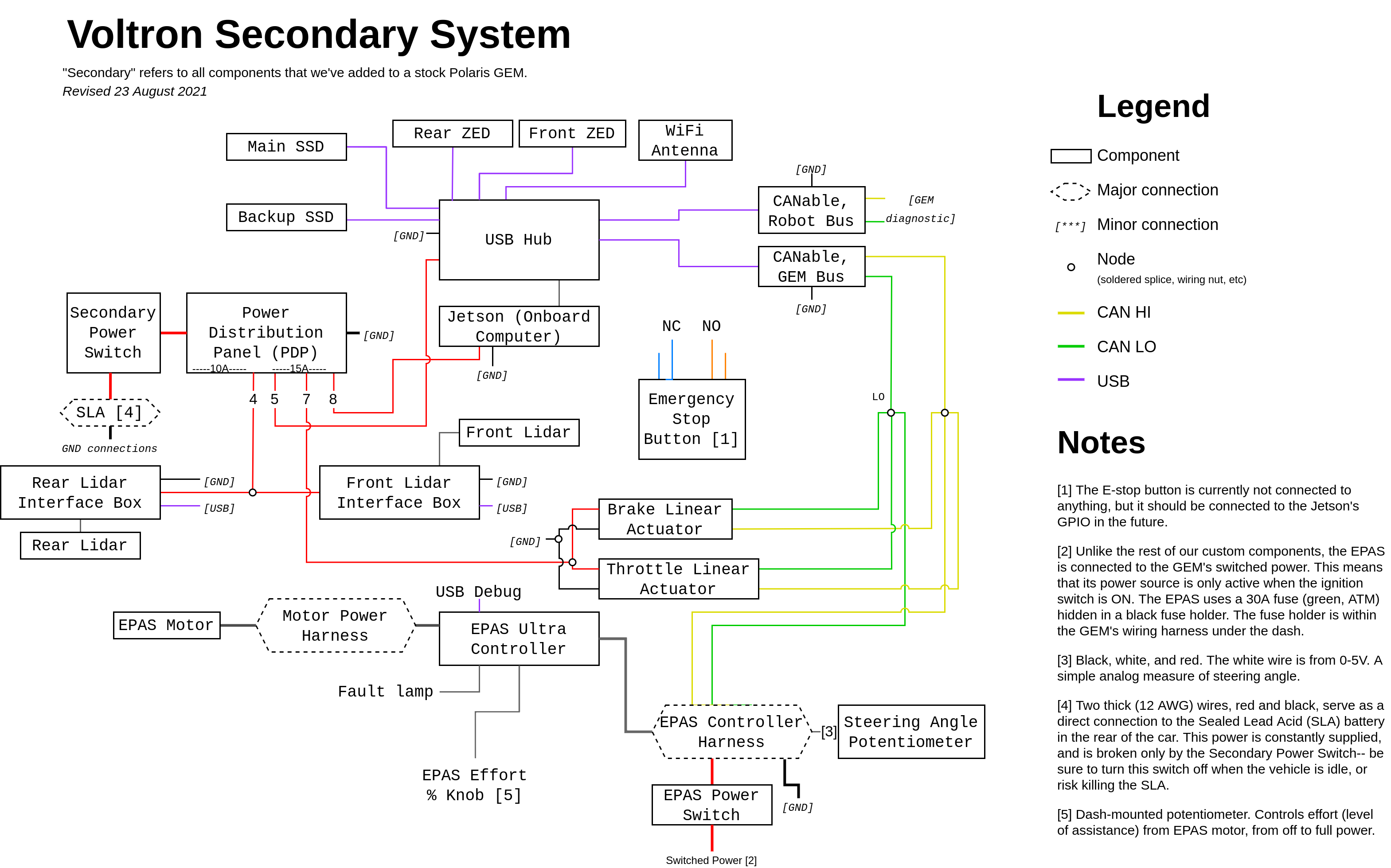
Below is a schematic of our “secondary” system. This refers to all the components that we’ve added onto the stock Polaris GEM from the factory. You can click the schematic to enlarge it.